Executive Summary
Wi-Fi networks are the most volatile because they’re subject to external factors that are the most difficult to control. RF interference, fading, or channel access conflict driven by a sudden increase in users can induce jitter that causes throughput and performance to collapse. This “last-mile” Wi-Fi network jitter is compounded by today’s streaming fast data, voice, video and IoT applications that transmit huge volumes of data in unpredictable bursts, as well as virtualization jitter from the cloud environments that often host them. As a result, jitter has now become the leading cause of network throughput collapse.
Jitter on any segment of the path from the application server to the Wi-Fi AP (access point/ router), and finally to the user’s Wi-Fi connected device, can trigger a throughput reduction across the entire path. Therefore, it’s a mistake to think of the wired and wireless segments as separate. They are ultimately part of the same network, and adjustments to both are often required.
On the wired segment of the path from the application server to the AP, most network administrators try to address poor throughput by upgrading bandwidth and/or implementing optimization solutions that rely on compression, caching and deduplication designed to accelerate traffic by reducing its volume. They combine this with faster, higher capacity APs in Wi-Fi networks to provide better performance for more mobile devices in the same service area.
However, these approaches don’t work well for data that’s encrypted or already compressed, and they can’t effectively address jitter. In fact, they often introduce additional performance overhead and cause the incidence of jitter-induced throughput collapse to increase, even in the most well architected networks. To understand the reasons for this and how to address it, it’s important to first understand the basics of TCP data transfer.
TCP Overview
When TCP accepts a stream of data from a server, it breaks it into a series of sequenced packets that are reassembled in the same order by the receiving client application. When TCP was designed over 40 years ago, the focus was on guaranteeing orderly packet delivery between endpoints. Based on the nature of applications deployed at the time, the underlying assumption was that network packets would arrive in relatively consistent time intervals unless the network became congested due to too much traffic, or some hardware failure in the path.
To guarantee packet delivery and guard against data loss, TCP relies on two variables to measure congestion and control throughput: a Retransmission Timeout (RTO) value based on a moving average calculation of the Round-Trip Time (RTT) for each packet to be sent and an acknowledgement (ACK) to be received, and a Congestion Window (CWND) that defines the maximum amount of data that can be sent through a connection. TCP sets its retransmission timer to the RTO value as it’s sending each packet. If an ACK isn’t received before the retransmission timer expires, the unacknowledged packet is retransmitted, as TCP flags the packet as dropped. With each retransmission attempt the RTO value is increased, and CWND is reduced on the assumption the network has become congested, leading to a decrease in throughput to avoid data loss. After three RTOs throughput is halved. After seven RTOs throughput collapses because TCP treats the packets as lost rather than merely delayed, and prevents traffic from being sent. After a sub-second waiting period, TCP begins its recovery process by incrementally increasing CWND with each successful packet transmission back to its pre-RTO, or pre-collapse level. This means TCP’s recovery process effectively doubles the impact of RTOs, by doubling the amount of time available bandwidth is underutilized, and throughput and performance are suboptimal.
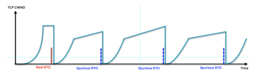
Contrary to TCP’s original design assumptions of orderly packet delivery in relatively consistent time intervals, today’s streaming applications generate network traffic characterized by periodic bursts of data that cause significant variation in RTT. This RTT variance, or jitter frequently triggers spurious RTOs, causing TCP to react as if the network is congested, reducing throughput by reducing CWND to prevent data loss even though plenty of bandwidth is available. The rapid adoption of cloud services and “last-mile” mobile and Wi-Fi networks add jitter of their own to today’s network environments.
Wi-Fi Jitter Triggers Throughput Collapse Over the Entire Network Path
All Wireless networks operate at the Physical and Data Link layers – layers one and two of the Open Systems Intercommunication (OSI) seven-layer model that defines functionality for network communications. Wi-Fi systems use these layers to format and control the data to conform with 802.11 wireless network communication standards. Wi-Fi layer one physical bandwidth is set by the Dynamic Rate Switching (DRS) algorithm running on the user’s laptop, tablet, or mobile phone based on the radio frequency (RF) signal to noise ratios detected by the user’s mobile device. DRS adjusts the mobile device’s data transfer rate to reduce retransmissions in response to RF interference, which typically increases with distance from an AP. If the data transfer rate remains high when there is significant RF interference, it will result in so many retransmissions and corresponding RTOs that throughput and performance decline dramatically.
Wi-Fi layer two channel access time varies depending on the number of mobile device Wi-Fi transmitters accessing an AP, and the traffic patterns generated by applications running on those devices. The more Wi-Fi transmitters located near each other, the greater the likelihood of channel access conflict, as numerous devices try to access the same channel simultaneously for uploads or downloads. That’s why it’s not uncommon for throughput to suddenly collapse at sports arenas, conference centers and other public venues when the number of users goes from zero to thousands in a matter of minutes, overwhelming the available Wi-Fi infrastructure.
The server connected to the wired segment of the path will also drop its transmission rate in reaction to RTOs triggered by RF interference and/or channel access conflict on the Wi-Fi last hop to avoid packet loss, even though plenty of bandwidth is available across all segments of the end-to-end path. Compounding these issues is the fact that maximum RTO impact occurs on short distance networks. In busy high-speed mobile and Wi-Fi networks with short RTTs and high jitter, the impact of RTOs misinterpreted as congestion can be devastating, causing up to a ten-fold reduction in throughput over the entire network path back to the server.
TCP’s response to jitter becomes the bottleneck over the entire network path from the sending server transmitting data over the wired segment to the wireless last mile, preventing full use of available bandwidth and delivering a poor user experience.
Standard Approaches Fall Short
Most network administrators try to address poor throughput by upgrading bandwidth and implementing optimization solutions on the wired portion of the path leading to the AP, combined with increasing Wi-Fi network bandwidth by introducing additional high capacity, high speed APs to provide better performance for more mobile devices in the same service area.
Over the wired portion, network optimization solutions include deduplication, compression, and local caching to reduce bandwidth usage, with traffic shaping to prioritize selected applications. While these techniques can yield some benefits, none of them tackle jitter-induced throughput collapse. In addition, techniques such as deduplication and compression can’t accelerate traffic that’s already compressed, and they require access to the payload. With the mass rollout of end-to-end encryption, this need for payload access introduces the added performance overhead of encryption/decryption at each endpoint, as well as the risk of exposing sensitive security keys to third-party vendor solutions.
Wi-Fi network bandwidth can be upgraded by deploying faster APs that support 5Ghz signals, offering up to 8x more channels than previous generation 2.4Ghz APs. However, it’s usually not possible to take advantage of all this added bandwidth. If channels aren’t appropriately spaced, deploying 5Ghz will lead to adjacent channel interference (ACI), another source of Wi-Fi jitter that leads to poor throughput. In addition, 5Ghz Wi-Fi signals are much shorter range, resulting in more fading, and have a harder time penetrating walls and other obstacles. Finally, not all devices support 5Ghz.
More APs can be added to a Wi-Fi network to reduce RF interference, which along with fading tends to increase with distance from an AP, causing packet loss and retransmissions. However, since APs, like the end-user devices that connect to them are also Wi-Fi transmitters, adding more APs often leads to greater RF interference in the form of co-channel interference (CCI) or crosstalk that becomes another source of jitter. CCI occurs when APs interfere with each other by using the same channel or radio frequency to transmit and receive Wi-Fi signals. It’s virtually unavoidable despite the best efforts of network architects to space APs appropriately apart, even in large public Wi-Fi networks.
Tackling Jitter Head-on
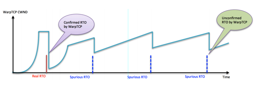
To properly address jitter, the first step must be to determine whether congestion is real, or TCP is reducing throughput in reaction to jitter misinterpreted as congestion from applications that generate traffic in inconsistent bursts, and/or jitter from common Wi-Fi network issues such as RF interference, fading and channel access conflict. In effect, TCP is often the bottleneck.
Badu Networks’ patented WarpTCP™ technology offers the only solution focused squarely on this TCP bottleneck issue for both wired and wireless networks. WarpTCP analyzes traffic in real-time to determine if congestion exists, and prevents TCP from unnecessarily reducing throughput in response to spurious RTOs due to jitter. WarpTCP’s proprietary algorithms determine actual bandwidth available to a TCP session in real-time, so the impact of transient fluctuations in RTT and packet loss are filtered out. WarpTCP was specifically designed to deal with rapidly changing bandwidth, loss patterns, server loads, and RTT variance, enabling it to do well in volatile environments like mobile and Wi-Fi networks. WarpTCP improves both 5 download and upload throughput by as much as 10x in wireless environments, even when the client is far from the AP, and the Wi-Fi connection is subject to greater RF interference and channel access conflict.
WarpTCP’s algorithmic approach to optimization offers another key advantage now that over 80% of internet traffic is encrypted or compressed: since WarpTCP doesn’t rely on compression and deduplication that require access to the payload, it eliminates the performance overhead of encryption/decryption at each endpoint, as well as the additional security risk of exposing encryption keys. This means performance stays at consistently high levels for all types of traffic: unencrypted, encrypted, or compressed, even in the face of extreme fluctuations.
WarpTCP™ Architecture
WarpTCP consists of two components that work hand in hand to prevent TCP throughput collapse and optimize the use of all available bandwidth for maximum performance:
- A TCP de-bottleneck module that implements WarpTCP’s proprietary algorithms that determine if jitter is due to congestion based on actual bandwidth available to each TCP session in real time, and prevent TCP from reducing the size of the congestion window (CWND) and hence throughput if it’s not
- A Transparent TCP Proxy that implements TCP session splicing by splitting the connection between the server and the client into two independent sessions. Each spliced server-to-client TCP session is replaced by a server-to-proxy sub-session and a proxy-to-client sub-session. The two sub-sessions have independent sequence numbers, as well as independent ACK flows. WarpTCP retains the IP addresses and port numbers associated with the original TCP source and destination to map them to the new sub-sessions.
This session independence enables WarpTCP to implement its own flow control algorithms based on speed matching that are far superior to TCP’s. With speed matching, the proxy receives as many packets as possible, as fast as possible, buffers them without modification, 6 and then forwards them to the client at different speeds and times. Speed-matching enables another performance enhancing feature – opportunistic bursting. Opportunistic bursting allows WarpTCP to fill-in unused gaps in bandwidth with packets that would otherwise be stalled. These capabilities are implemented in a multi-core, multi-threaded architecture that supports over 5 million parallel TCP sessions, enabling use cases that are well beyond the reach of anything else on the market.
Finally, although WarpTCP is transparent to users, its architecture enables dramatic improvement in one of the most visible aspects of user experience – page load times. Browsers only support establishment of two to four TCP sessions simultaneously, whereas a web page can easily have over 100 objects, each requiring its own TCP session to send and receive data. Since WarpTCP connections with the browser are independent of the server and can be established in parallel, pages typically load 2-3x faster.
Deployment Options
WarpTCP requires no changes to clients or servers, and can be installed at any single point on the network closest to the source of jitter, unlike competing dual-ended optimization offerings. However, jitter on any segment of the network path from an application running in an onpremises data center or a cloud environment, to the user’s Wi-Fi connected device can trigger a throughput collapse. For this reason, Badu offers solutions for both wired and wireless networks that leverage WarpTCP. When deployed in combination, they complement each other to filter out the impact of jitter over the entire path between the origin server and the end-user. Examples of typical deployment scenarios are discussed below.
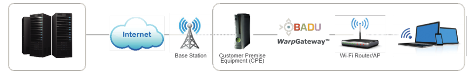
Wi-Fi Deployment
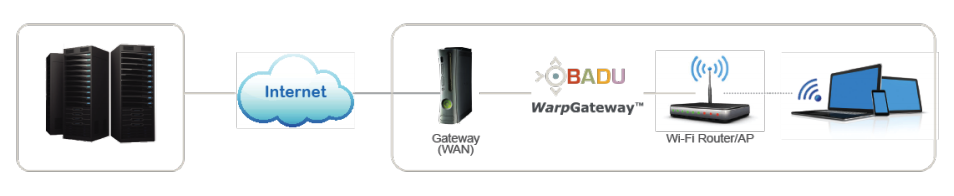
In Wi-Fi networks, Badu’s WarpGateway™ is installed between the WAN gateway modem connecting the home or business to the internet and the Wi-Fi AP/Router. Once installed, WarpGateway filters out the impact of jitter caused by fading, as well as RF, cross channel and adjacent channel interference that can lead to throughput collapse over the entire path.
5G FWA Deployment
When 5G FWA (Fixed Wireless Access) is implemented, the deployment architecture is essentially the same, with the mobile network operator’s CPE (Customer Premises Equipment) which converts the 5G signal into Wi-Fi taking the place of the gateway as shown below. In a 5G FWA environment, WarpGateway will continue to filter out the impact of jitter on Wi-Fi performance and throughput.
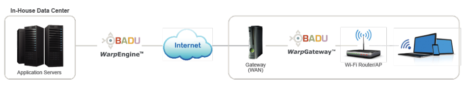
In-House Data Center to Remote Branch Office
To address jitter caused by applications hosted at in-house data centers, WarpEngine™ can be installed on the network close to the servers to filter out the impact of application jitter to prevent it from triggering throughput collapse. WarpEngine installed at the data center complements WarpGateway installed at branch office locations to eliminate Wi-Fi jitter. WarpEngine can work in conjunction with existing WAN optimization solutions and ADCs used to balance workload across servers at the data center.
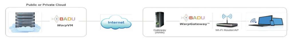
Cloud Architecture
To eliminate poor performance caused by cloud-hosted application jitter, as well as virtualization jitter due to VM crosstalk and hypervisor packet transfer delays, a WarpVM™ instance can be installed in any public or private cloud environment, working in combination with WarpGateway behind the firewall to prevent Wi-Fi jitter, as shown in the diagram below.
Conclusion
Actual user experience in a Wi-Fi network is almost always impacted by the “last mile” between the Wi-Fi router (AP) and the mobile device. This Wi-Fi “last mile” is the most volatile because it’s subject to external factors that are more difficult to control. Jitter from RF interference and channel access conflicts can instantly arise with any sudden and dramatic increase in users – a common scenario in Wi-Fi networks at sports stadiums, tourist destinations and other public venues. Jitter originating on the Wi-Fi network also causes TCP on the wired portion between the server and the AP to treat any RTT variance as congestion, slowing the transmission rate. When Wi-Fi jitter is combined with jitter on the wired portion of the path driven by the nature of today’s streaming fast data, voice, video and web application traffic, throughput collapses and applications stall. This occurs even though plenty of bandwidth is available.
Only Badu Networks’ patented WarpTCP technology deals directly with the problem of jitter-induced throughput collapse on both wired and wireless networks and offers a solution that future-proofs your network for 5G. WarpTCP’s unique patented ability to algorithmically determine in real-time whether congestion exists, and prevent TCP from reducing throughput when plenty of bandwidth is available, addresses TCP’s reaction to jitter head-on. As a result, only WarpTCP eliminates today’s most common cause of network throughput collapse and poor user experience, as well as the unnecessary risk, disruption and expense of network infrastructure upgrades.
Click here to see a Free Demo of WarpEngine™
You’ll see how WarpTCP™ performs in various real-world network use cases
and gain a better understanding of what the management interface looks like,
how it operates, and the benefits it can provide.